 When the central computer/network equipment hall of Tilburg University got
new climate control equipment, the Unix system managers were anxious to get
relevant information (mostly temperature readings) fed directly into their
Nagios monitoring system. Several
solutions were available, but none of them really looked good. So I set out
to create a simple, low-tech, cheap, but reliable and professional solution
to solve their request.
When the central computer/network equipment hall of Tilburg University got
new climate control equipment, the Unix system managers were anxious to get
relevant information (mostly temperature readings) fed directly into their
Nagios monitoring system. Several
solutions were available, but none of them really looked good. So I set out
to create a simple, low-tech, cheap, but reliable and professional solution
to solve their request.
Update, 2025-05-16
No, I did not do anything really, but Chris Petrich has published a few interesting details about the DS18x20y.Update, 2009-09-08
Today I completed another copy of the sensor array, in a different enclosure but with the same circuit. With a flat Ubuntu Jaunty (9.04) installation, providing DigiTemp v3.5.0, exactly the same instructions as for Debian Sarge are in effect. It still works like a charm. I then made a tiny change: the VDD pin of the DS1820 now is not clipped off, but connected to GND. This may suppress a bit of noise that could influence reliability on long wires. Both variants work.
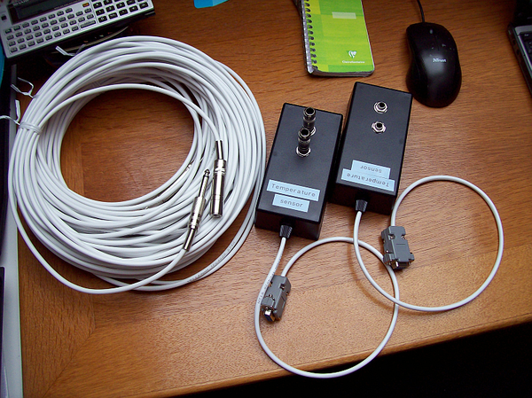
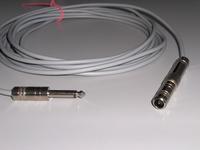
↑ Two sensor units containing the circuit, this time with just two connectors plus plus one internal sensor. Four 10m extension cords allow for a wide range (much more is possible). As with the larger unit below, the actual DS1820 sensors are mounted inside metal 6.3mm jack plugs.
Background
 I got inspired by an
article by Stefan Blechschmidt, in which he describes a basic circuit
and software to wire up a Dallas
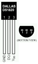
Semiconductor (now merged with Maxim) temperature sensor. The sensor is
called DS18S20 and
can be purchased at well-assorted electronics shops for about € 4.50.
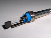
DS1820 sensors work exactly the same, but you likely get a DS18S20 anyway. I
did not modify the circuit at all (hard to do with so few parts!) but
focused on the embedding of the circuit in the equipment room and the
software environment.
I got inspired by an
article by Stefan Blechschmidt, in which he describes a basic circuit
and software to wire up a Dallas
Semiconductor (now merged with Maxim) temperature sensor. The sensor is
called DS18S20 and
can be purchased at well-assorted electronics shops for about € 4.50.
DS1820 sensors work exactly the same, but you likely get a DS18S20 anyway. I
did not modify the circuit at all (hard to do with so few parts!) but
focused on the embedding of the circuit in the equipment room and the
software environment.Update, 2010-07-30 Another variant of the sensor, called DS18B20, has been confirmed to work with this circuit as intended. Thanks to Greg Smith for the information.
I needed several sensors. The DS18S20 was perfect for this, as this device
is designed for the 1-Wire® bus system.
Actually this means that you need two wires, but these two wires carry both
power and data. All devices you want are simply put in parallel on the two
wires, which may run for several hundred meters. The factory burns a 64-bit
unique identifier in each sensor device, which enables the host machine to
both list all devices on the bus and address each device individually.
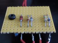
The host machine needs a small circuit to convert the 1-Wire bus to something that can be connected to a standard RS232 connector, although the protocol is not at all RS232.
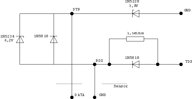
Basically this circuit converts the RS232 signal levels to 5V and makes sure that the devices can get power in between data transfer bursts. With only five simple components, the cost does not exceed € 2 and the whole circuit can be crammed into a standard 9-pin D connector shell, as this article shows. However, I needed a different packaging solution.

| Description | DB-25 | DB-9 | Sensor |
CAUTION! Many people including myself at one point in time
printed out this page and glanced at this table
when building the plug connections. It is too easy to mix up
the DB-25 and DB-9 columns this way, and as you can see, RXD and TXD are
exactly opposite. Just cross out the wrong column. And, be careful to which GND you connect the DB shells. Your target is to avoid earth ground (shielding ground) to more than one place. If your computer connection cable has shielding which is already grounded at the computer's side, do not connect it to earth ground at the array side as well. |
| DTR | 20 | 4 | Data (PIN 2) | |
| RXD | 3 | 2 | GND (PIN 1) | |
| TXD | 2 | 3 | ||
| GND | 7 | 5 |
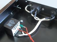
Two wires go to the sensor connector panel.
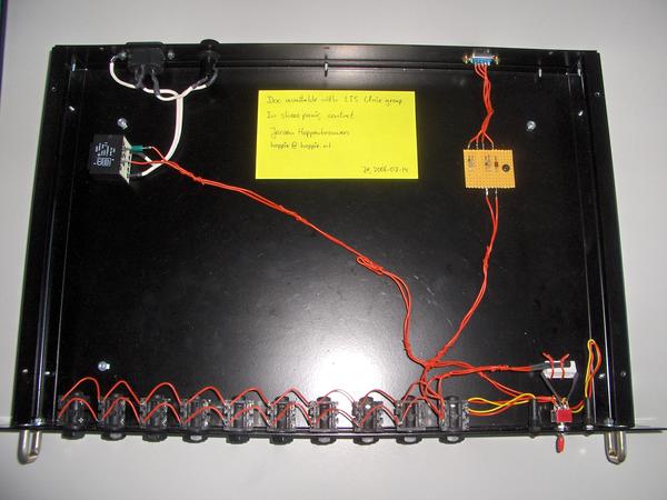
At the bottom left, you see ten 6.3mm sockets that accept the sensors, either directly (useful for testing) or via an extension cord. All these sockets are in parallel, so they are unnumbered. And you may toy around whatever you want as long as all sensors remain parallel on the two wires.
 At the bottom right, you see two 12V LEDs, a switch, a 82Ω/5W resistor,
and another DS18S20 temperature sensor. The purpose of this assembly is to
provide for a no-brains el cheapo warning that the power of the hub has
been cut. In my particular application, the equipment room has a large
no-break power supply and a diesel generator for emergency power. However,
there was no means to feed the status of this system into Nagios yet. In the
equipment room, there are a few power outlets that are not on the
no-break unit; we call them sense outlets. One of these sense outlets
feeds the transformer of the hub. I use a normal DS18S20 temperature sensor to
sense the presence of power, as it heats up the resistor to about 50°
Centigrade. If the power is cut, the temperature of the resistor drops at about
5°C per minute. This is quick enough to let Nagios know the status of the
non-no-break power (after all, if somebody is present at the site, there will
be plenty of other indications that something is wrong). The (DPDT, six-lead)
switch lets the operator select whether the sense power is fed to the resistor
(normal position) or to a red 12V LED (test position). The other LED is green
and simply indicates the presence of sense power. As a bonus, there always is a
temperature sensor on the bus this way, which is handy for testing no matter
what temperature it is at.
At the bottom right, you see two 12V LEDs, a switch, a 82Ω/5W resistor,
and another DS18S20 temperature sensor. The purpose of this assembly is to
provide for a no-brains el cheapo warning that the power of the hub has
been cut. In my particular application, the equipment room has a large
no-break power supply and a diesel generator for emergency power. However,
there was no means to feed the status of this system into Nagios yet. In the
equipment room, there are a few power outlets that are not on the
no-break unit; we call them sense outlets. One of these sense outlets
feeds the transformer of the hub. I use a normal DS18S20 temperature sensor to
sense the presence of power, as it heats up the resistor to about 50°
Centigrade. If the power is cut, the temperature of the resistor drops at about
5°C per minute. This is quick enough to let Nagios know the status of the
non-no-break power (after all, if somebody is present at the site, there will
be plenty of other indications that something is wrong). The (DPDT, six-lead)
switch lets the operator select whether the sense power is fed to the resistor
(normal position) or to a red 12V LED (test position). The other LED is green
and simply indicates the presence of sense power. As a bonus, there always is a
temperature sensor on the bus this way, which is handy for testing no matter
what temperature it is at.
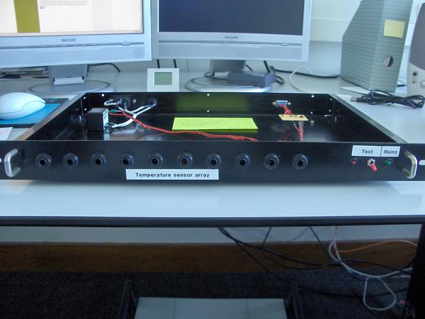
↑ The finished hub without top panel, front view. ↑
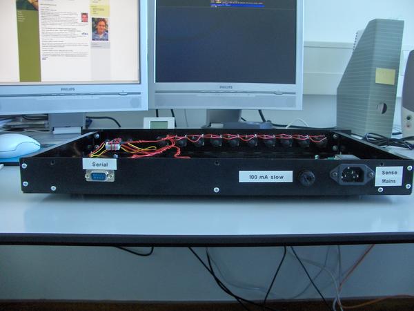
↑ The finished hub without top panel, rear view. ↑
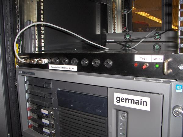
↑ The hub in the 19" rack. Not all sensors installed, yet.↑

↑ The hub in the 19" rack. ↑
Software Implementation
You will have to install and configure a few separate units:- the Digitemp low-level sensor driver,
- a cron script to write the temperatures to a state file every n minutes,
- a Nagios plugin that reads the state file for temperature info.
The Digitemp low-level sensor driver
The main driver for the sensor array is Digitemp, a mature application written by Brian C. Lane. Both the old version 1.3 and the latest and greatest (currently 3.3, but look here for the official site) work correctly. Debian maintains a clean digitemp package if you prefer .deb over hand work. Just install it:
# apt-get install digitemp
Recent Digitemp releases are mostly aimed at the use of more complex
circuits using dedicated chips. If you use one of these recent releases,
make sure that you select the executable intended for the simple case. This
seems to be digitemp_DS9097 on my Debian Sarge (current stable)
systems. You do not need any of the fancy additions, such as MySQL and what
not, unless you actually want the functionality these tools give you. For
Nagios integration, you only need the simple digitemp executable; I would
make a symlink which typically goes into the /usr/local/bin
directory:
# ln -s /usr/bin/digitemp_DS9097 /usr/local/bin/digitemp
However, you may also use the full executable name in the scripts that
follow. Your choice.
You now must make sure that the user that later will run the digitemp command (from cron) has access to the serial port you attached the devices to (typically /dev/ttyS0):
# adduser <digitemp-user> dialout
I normally first let digitemp poll the bus for all available devices
and write their ROM addresses to a config file. Dependent on where you want
the file, you may need to run as root.
# digitemp -i -c /usr/local/etc/digitemp.conf -s /dev/ttyS0
Of course, your configuration file will be slightly different. Mine looks
like:
DigiTemp v3.3.2 Copyright 1996-2004 by Brian C. Lane
GNU Public License v2.0 - http://www.brianlane.com
Turning off all DS2409 Couplers
.....
Searching the 1-Wire LAN
10805902010800AD : DS1820/DS18S20/DS1920 Temperature Sensor
10B196020108003A : DS1820/DS18S20/DS1920 Temperature Sensor
10F3EC02010800F1 : DS1820/DS18S20/DS1920 Temperature Sensor
104FFC02010800F7 : DS1820/DS18S20/DS1920 Temperature Sensor
10FFB102010800F5 : DS1820/DS18S20/DS1920 Temperature Sensor
ROM #0 : 10805902010800AD
ROM #1 : 10B196020108003A
ROM #2 : 10F3EC02010800F1
ROM #3 : 104FFC02010800F7
ROM #4 : 10FFB102010800F5
Wrote /usr/local/etc/digitemp.conf
TTY /dev/ttyS0
You might want to reorder the sensor numbers (ROM 0, 1, 2...) that
digitemp selected to match the numbers you have stuck on the
individual sensors. I made the built-in power presence sensor #0. Make sure
that you have the right sensor numbering by selectively plugging them into
the bus and querying only this one sensor with the -t switch (needs no root
any more):
READ_TIME 1000
LOG_TYPE 1
LOG_FORMAT "%b %d %H:%M:%S Sensor %s C: %.2C F: %.2F"
CNT_FORMAT "%b %d %H:%M:%S Sensor %s #%n %C"
HUM_FORMAT "%b %d %H:%M:%S Sensor %s C: %.2C F: %.2F H: %h%%"
SENSORS 5
ROM 0 0x10 0x80 0x59 0x02 0x01 0x08 0x00 0xAD
ROM 1 0x10 0xB1 0x96 0x02 0x01 0x08 0x00 0x3A
ROM 2 0x10 0xF3 0xEC 0x02 0x01 0x08 0x00 0xF1
ROM 3 0x10 0x4F 0xFC 0x02 0x01 0x08 0x00 0xF7
ROM 4 0x10 0xFF 0xB1 0x02 0x01 0x08 0x00 0xF5
$ digitemp -c /usr/local/etc/digitemp.conf -t 0
If later on you discover that a sensor once in a while suddenly produces the
figure of 85.0 °C (exactly), increase the READ_TIME value. This
problem is caused by not allowing the sensor enough time to complete its
conversion and transmit cycle.
DigiTemp v3.3.2 Copyright 1996-2004 by Brian C. Lane
GNU Public License v2.0 - http://www.brianlane.com
Aug 07 15:10:05 Sensor 0 C: 23.69 F: 74.64
The cron script
The polling of the sensors is not re-entrant, i.e., it would be a bad idea to let Nagios do the polling directly, as Nagios may fire overlapping requests and a request can take up to five seconds. The result would be a bus collision and bad readings. So you have to create a small cron script (in bash or whatever) that polls all sensors (-a) every n minutes. The result of this polling you write to a file /var/lib/temperature/current
#!/bin/bash

# get_temperature: polls the temperature sensor array and leaves the

# temperatures in a state file. Called by cron every 5 minutes.


TMPFILE=/tmp/temperature.XXXXXX

STATEFILE=/var/lib/temperature/current

DIGITEMP=/usr/local/bin/digitemp

DIGICONF=/usr/local/etc/digitemp.conf


# Abort after first script error.

set -e


# Get a unique temporary tamper-proof file name.

tmp=$(mktemp $TMPFILE)


# Create a full poll list of the temperature array. This takes up to

# 5 seconds per sensor, and therefore must be done to a (slowly growing)

# temporary file.

$DIGITEMP -c $DIGICONF -a -q > $tmp


# 'Atomically' move the freshly created state file in place.

mv $tmp $STATEFILE
Put this file in the /usr/local/bin directory; I call it /usr/local/bin/get_temperature. Tell cron to run this job every five minutes by creating the file /etc/cron.d/get_temperature:
# Poll the temperature sensor array every five minutes.
In this example the script is run as root, but you certainly do not need
to do this, you may run the script as any user that has access to the TTY
port.
*/5 * * * * root /usr/local/bin/get_temperature
# Append the last poll to the history file after each whole hour.
4 * * * * root cat /var/lib/temperature/current >>
/var/log/temperature.log
The second cron command above simply concatenates the state file (current temperatures) to a history file that you might want to keep to create statistics. Totally optional.
The Nagios plugin script
The actual Nagios plugin checks only the temperature state file, usually every five minutes. I changed an existing plugin to work with temperature bands instead of just maxima, as I want to monitor whether temperatures get out of hand, either up or down. I don't show the whole script inline, but you can download it here. It contains documentation on how to install the script in Nagios, but this is fully standard.Here is the usage output of the Perl script for good measure:
check_temperature v1.1 - Nagios Plugin
Copyright 2006 Jeroen Hoppenbrouwers <hoppie@hoppie.nl>
More info: http://www.hoppie.nl/tempsens/
See source for License and Nagios config example.

Usage:
 check_temperature -s sensor -t target -w warn -c crit

Options:
 -s n             DigiTemp Sensor #, default 0
 -t temperature   Target temperature in Centigrade, default 20
 -w deviation     Temperature deviation from target to warn (required)
 -c deviation     Temperature deviation from target when critical (required)

Output:
 UNKNOWN/-1, OK/0, WARNING/1, CRITICAL/2
Conclusion
The result of all this is a simple but robust solution to feed Nagios with temperature measurements, which is an essential part of environmental monitoring in many professional ICT operations.